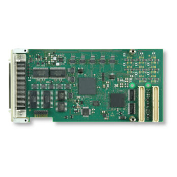
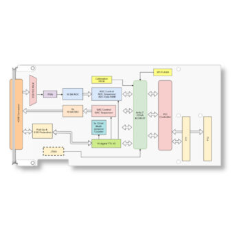
The TPMC851 combines 32 single ended / 16 differential channels of 16 bit multiplexed analog input, 8 channels of 16 bit analog output, 16 digital I/O lines and two 32 bit multi-purpose counters on a standard single-width PMC module.
A 16 bit ADC converts 32 single-ended or 16 differential multiplexed ADC input channels. The conversion time is up to 1.25 µs without channel/gain change and up to 17.25 µs with channel/gain change (ADC throughput rate up to 250ksps). The input multiplexer of the A/D circuit offers analog overvoltage protection of up to 70Vpp. A programmable gain amplifier allows gains of 1, 2, 4 or 8 resulting in input voltage ranges of ±10V, ±5V, ±2.5V or ±1.25V.
The ADC part of the TPMC851 can operate in Manual Mode or Sequencer Mode:
Manual Mode
In Manual Mode the multiplexer, programmable gain amplifier and the converter are fully controlled by the user. A conversion for a selected channel / gain can be started automatically after the settling time has elapsed, or manually by the user.
Sequencer Mode
In Sequencer Mode each of the A/D channels can be independently enabled and configured for the sequencer. The sequencer can run continuously, at specific time intervals, or it may be triggered by an external event. Conversion data is stored in a data RAM.
The 8 analog output channels are realized by eight 16 bit digital to analog converters (DACs). The conversion time is 10 µs. An operational amplifier drives the full-scale range of ±10V and is capable to drive high capacitive loads. Similar to the analog inputs a sequencer can control the analog outputs.
Following operation modes are available:
Immediate Update: Updates the DAC output immediately when new data is written to the DAC channel.
Simultaneous Update: DAC data is buffered and all DAC outputs are updated simultaneously on a trigger event:
- Manual Update: Updates all DAC outputs on a manual event (register write)
- Trigger Update: Updates all DAC outputs on a external event
- Sequencer Update: Updates all DAC outputs after the sequencer timer has elapsed
For each individual TPMC851 card, A/D and D/A correction values are obtained during the factory acceptance test and are stored in an on-board EEPROM.
The 16 digital TTL tri-state I/O lines with 4.7k& pull up resistors are ESD protected and protected against overvoltage. All 16 lines can be individually programmed as input or output, and can generate an interrupt on negative and positive transitions. Each input has an electronic debounce circuit to prevent short spikes on the input lines to cause an interrupt. The digital inputs can supply the external signals for the ADC and DAC sequencer and the 32 bit counter.
Additionally the TPMC851 offers two 32 bit multi-purpose counters. The counters include a 32 bit preload register and a 32 bit compare register. The 32 bit counters can be fed with an internal clock or with an external signal supplied by the digital inputs. The 4 counter input modes determine the interpretation of the input signals. Additionally 3 count modes, which describe the behavior of the counters, and 4 control modes are available:
Counter Input Modes
- Internal clock with prescaler
- Up/Down count
- Direction count
- Quadrature count with 1x, 2x or 4x resolution multiplier
Count Modes
- Cycling Counter
- Divide-by-N
- Single Cycle
Control Modes
- Load on Control
- Latch on Control
- Gate on Control
- Reset on Control
Software Support (TPMC851-SW-xx) for different operating systems is available


