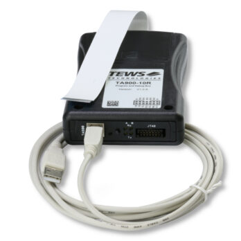
The TA900 is an Interface Box which can be used to program and debug hardware modules providing a corresponding connector.
The Interface Box connects to compatible modules via a 20-pin Flexible Printed Circuit (FPC) Connector which can provide access to the module's JTAG Chain and the additional interfaces A and B.
The TA900 can be accessed by USB 2.0 and by a 14-pin JTAG Header, and is equipped with a Pushbutton Switch which is offering the possibility to send an impulse to one of the connected module's I/O pins.
A green LED indicates the assertion of this impulse by interrupting illumination.
In case of the user programmable FPGA boards TAMC631 and TAMC640/641, Interface A provides access to the UART of the onboard Module Management Controller (MMC), and Interface B connects to two user pins of the module's onboard FPGA. If a UART core is implemented in the module's FPGA, serial communication via Interface B is possible.
By setting DIP Switches, the provided yellow LEDs located in the TA900 front panel can either indicate the logic level of the Interface's lines or can be configured to visualize serial communication on the Rx and Tx lines, if they are connected to the UART interfaces of the USB Controller.
Level Shifters can handle I/O voltages between 1.2V and 3.3V at the FPC Connector which offers a wide range of possible configurations for Interface A, B and the JTAG Chain of the connected hardware module.
The JTAG Chain of the connected hardware module which is useful to program and debug onboard devices can be accessed in two different ways:
If it is accessed via the 14-pin Header, which must be the case when communicating with Xilinx Devices, a "Xilinx Platform Cable USB II" (which is required) can be connected without any adaption.
If the JTAG Chain is accessed via the USB interface, Channel A of the USB Controller is not used to communicate with Interface A, but to generate JTAG signals for debugging or programming reasons. In this configuration, Lattice Devices for example can directly be programmed without the necessity of an additional Programming Cable, as the TA900 is directly supported by Lattice's Software Tool "ispVM".
The TA900 is self-powered by the FPC Connector which means that it is not necessary to connect the Interface Box to USB to provide a supply voltage.
The Interface Box meets the requirements to operate in extended temperature range from -30° to +75°C and comes with a USB A to USB B Cable and an FPC Flexcable.
