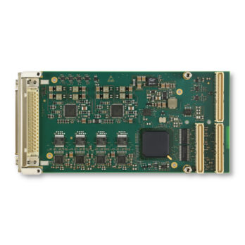
The TPMC541 is a standard single-wide PCI Mezzanine Card (PMC) compatible module providing:
- A PCI Master capable 32 bit 33 MHz PCI interface
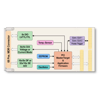
- 8 Tristate-Capable bi-directional 5V-tolerant LVTTL/TTL compatible General Purpose Digital I/O Lines (Front I/O)
- Up to 8 Single-Ended 16 bit Analog Outputs in (bipolar or unipolar) Voltage Mode or (unipolar) Current Mode (Front I/O)
- Up to 32 Single-Ended or 16 Differential 16 bit bipolar Analog Inputs (Front I/O)
- Tristate-Capable bi-directional 5V-tolerant LVTTL/TTL compatible Digital I/O Lines for Conversion Control Signals (Conversion Clock, Frame Trigger) (Rear-I/O)
Digital I/O
The TPMC541 features 8 ESD protected, interrupt and tristate-capable bi-directional general purpose digital I/O lines at the front I/O connector. Each digital I/O line features a pull resistor to a common reference (+3.3V, +5V or GND).
Analog Outputs
The TPMC541R-10R order option provides 8 (eight) analog output channels while the TPMC541R-20R order option provides 4 (four) analog output channels.
Each individual D/A channel can be configured to operate in any of the following output ranges:
- 5V, 6V, 10V or 12V unipolar Voltage Ranges
- ±5V, ±6V, ±10V or ±12V bipolar Voltage Ranges
- 4mA to 20mA Current Range
- 0mA to 20mA (or 24mA) Current Range
The TPMC541 provides a D/A Sequencer unit for performing periodic simultaneous digital to analog conversions at a configurable conversion rate.
Analog Inputs
The TPMC541R-10R order option provides 4 (four) ADAS3022 devices and up to 32 single-ended or 16 differential analog inputs. The TPMC541-20R order option provides 2 (two) ADAS3022 devices and up to 16 single-ended or 8 differential analog inputs.
Each ADC device configured for Single-Ended Input Configuration provides the following input voltage ranges (single-ended and referenced to ground): ±0.64V, ±1.28V, ±2.56V, ±5.12V, ±10.24V, ±12.288V.
Each ADC device configured for Differential Input Configuration provides the following differential input voltage ranges: ±0.64V, ±1.28V, ±2.56V, ±5.12V, ±10.24V, ±20.48V, ±24.576V.
The TPMC541 provides an A/D Sequencer unit for performing a sequence of periodic analog to digital conversions at a configurable conversion rate.
Conversion Correction Data
Each TPMC541 is factory calibrated. Conversion data correction values are determined during the factory acceptance test and are stored in an on-board serial EEPROM unique to each PMC module. These correction values may be used to perform a hardware correction for every individual D/A channel and output range and for every individual A/D channel and input range.
Conversion Control Signals
Conversion clock signals may be generated on-board for internal use and may also be driven out on P14 rear I/O if the card is operating as a master card in a Multi-Board configuration. The conversion clock signals may also be sourced externally via the P14 rear I/O interface if the card is operating as a slave card in a Multi-Board configuration.
I/O Connector
The general purpose digital I/O signals, the analog output signals and the analog input signals are accessible on a 68 pos. Mini D Ribbon (MDR68) front connector.


